Powertrain
|
Welcome to the 2007/08 Powertrain section. This page will be updated frequently, so please keep checking for the most up-to-date information.
Aims
Produce a high performance, reliable Powertrain package, including the engine, induction system, exhaust system, cooling system, fuel system, lubrication and differential system. In addition to this, consideration will also go toward maintaining good fuel economy and reducing the weight of the Powertrain system. The overall package will provide the team a competitive car for the competition in July.
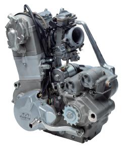
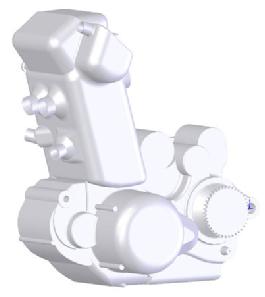
Engine
This year, the team have decided to use a 2006 KTM 525 cc single cylinder engine, primarily because of its high torque characteristics in the lower half of the rev/min range.
Drivetrain
Contains a multi disc clutch in an oil bath with a six speed sequential gearbox. The gearbox is connected to the rear wheels via chain drive and sprockets with a selected Quaife Differential unit.
Fuel System
The fuel system consists of the fuel cell (tank), fuel pump, fuel filter, regulator, electronic fuel injection unit and appropriate plumbing.
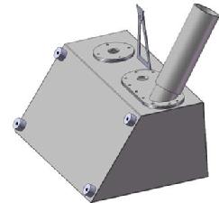
Intake System
The intake system is designed to deliver the air fuel mixture to the cylinders. It is made up of the throttle body, air filter and the runner. Due to the regulations of the Formula Student competition it is required to have an intake restriction of 20 mm downstream of the throttle. This makes it vitally important to make use of the available air that can be induced. A high performance intake aims to do the following:
A fixed length intake manifold will be the main research priority for the intake system. This is to optimise the power and torque of the engine. Computational Fluid Dynamic (CFD) analysis will be carried out on the intake manifold design using Ricardo Wave software and will then be manufactured and tested on a flow bench.
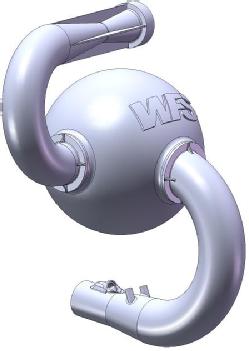
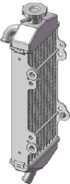
Cooling System
The WFS 2007/08 W7 cooling system consists of a liquid cooled, permanent rotation of cooling liquid through a mechanically driven water pump.
|
|
||||||||||||
|
|