Programming
|
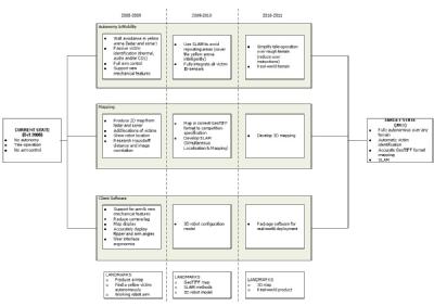
There are two programs, the first is a program which runs on the robot, reading the sensors and controlling the motors, as well as performing the mapping, identifying victims and making decisions when run in autonomous mode. The second program is a client program, which runs on a separate computer and communicates with the robot to allow remote control and monitoring of the robot. The programming for the robot is being written using Java, this makes it cross-platform, which is useful, since the on-board computer for the robot is running a cut-down command line version of linux (to save on system resources), whilst development and the client program are running on both linux and windows. Software Development Flow Chart
Devices Each of the sensors and actuators attached to the robot has a separate class to communicate with them and read or set their values. Classes have been written to communicate with the speed controllers, LADAR, LCD panel, I/O interface board and joystick control device. In addition, a serial communications class has been produced, which will speed up the development of classes for other devices. Communications To handle communications, it had been decided to utilise the TCP/IP computer networking protocol, which will allow communications to be transmitted through a variety of mediums using commercially available products, as such it will be capable of both wireless or wired operation. A server system has been built into the robot software, allowing remote clients to connect to it. This server has been written to be fully threaded to allow for multiple simultaneous connections, with authentication built in to prevent unauthorised access/control of the robot. Mapping A mapping class is being developed to store the data which the sensors pick up, to produce a map of the area around the robot. This map is based around the concept of an ‘occupancy grid’ whereby each point in the map has a probability as to whether or not there is something there or not, based upon the number and reliability of the readings taken for that point. From this data a map of the environment is built up, allowing for decision making and path-finding, as well as meeting one of the key requirements for the competition. Safety To ensure that the main on-board computer for the robot is fully functional and in control, a separate safety controller has been built into the robot. This listens to a serial port on the computer and must receive a regular ‘heartbeat’ from the main robot program. If this signal is not received, then the safety controller will cut the power to the motors, requiring a manual reset of the robot for it to continue. Additionally the safety controller can monitor the sonar sensors surrounding the robot and stop the robot from moving if a collision is imminent. When a client is connected to the robot and is controlling it remotely, a regular ‘heartbeat’ signal must be received by the robot from the client. This makes sure that the client is still connected and in control. If this is not received in a timely order, then the robot will cease moving. Finally there is an emergency stop button on top of the robot, which will cut all power to the robot when it is pressed. To restart the robot, the emergency stop button has to be reset, as well as a separate ‘reset’ button being pushed, which can only be done at the robot. |

