
Ultrasonic anememometer for Mars
Introduction - cMUTs on Mars?
There is a need for the measurement of wind velocity on the surface of other planets. One possible approach to this is to use gas-coupled cMUTs to send ultrasonic signals in counter-propagating directions, and thus to measure the time of flight changes. Acoustic anemometers are well established for use on Earth. This research in collaboration with Cornell University looked at cMUTs for possible use in an ultrasonic anemometer for a future NASA Mars lander. We are also collaborating with the Atmospheric, Oceanic and Planetary Physics Group at Oxford University and The Planetery and space sciences research Institute at The Open University to use Polymer membrane transducers on the European Exomars Lander.
The main challenges to such a measurement are:
The pressure at the surface of Mars is low (~6 mbar)
The atmosphere is mostly carbon dioxide.
Both of these factors will cause increased attenuation over measurements in air at atmospheric pressure.
The cMUT design differs from most other designs in being open to the atmosphere. This allows larger area single membranes to be constructed than would be possible with vacuum-sealed devices .
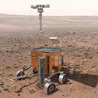
Figure 1: Proposed Exomars Lander (image courtesy of ESA)
Experimental procedure
Matched pairs of cMUTs were aligned in a vacuum chamber facing each other, with a separation of around 55 mm The 2mm square devices actually consisted of four 2mm devices arranged a 2 x 2 array and connected in parallel. A 20 V d.c. bias was applied. The receiver was connected to a Cooknell CA6/C charge amplifier and SU2/C power supply. The source drive signal was provided by a HP33120A arbitrary waveform generator through a power amplifier to give a maximum drive amplitude of 40V. Windowed swept frequency chirps with 40 ms duration were used. Operation at pressures down to 6mbar was possible in air and carbon dioxide.
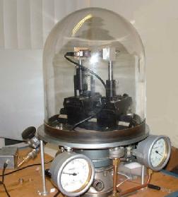
Figure 2: Schematic of equipment setup and a photograph of devices under test in the vacuum chamber.
Results
Figure 3 shows a typical waveform obtained in carbon dioxide at low pressure (~13 mbar), where it can be seen that indeed ultrasonic signals can be sent from one cMUT to another in conditions likely to be met on the surface of Mars.
Figure 3: Ultrasonic waveform (top) and corresponding spectrum (bottom) for a cMUT in carbon dioxide at 13 mbar.
Figure 4 shows a comparison between the measured centre frequency and that predicted by our simple model, assuming a nominal 100nm effective air gap. It can be seen that the experimental points agree well with theory, and that the peak frequency decreases with pressure.
Figure 4: Theoretical and measured variation of centre frequency with pressure for a 2mm x 2mm device in (a) Air and (b) Carbon Dioxide.
Figure 5 shows the FFTs for cMUTs at two gas pressures, but with two membrane thicknsses. It is seen that at atmospheric pressure the thinner membrane is better, but at lower pressures it is best to use the thicker membrane.
Figure 5: Ultrasonic spectra from cMUTs in air at 13 mbar (left) and atmospheric pressure (right).
Related references
L.A.J. Davis, D. A. Hutchins and R.A. Noble, “Characterisation of cMUTs in rarefied gases”, IEEE Trans. Ultras. Ferr. Freq. Contr. 54, 1065-1071 (2007).
L.A.J. Davis, D.A. Hutchins, R.A. Noble and D. Banfield, “The Characterisation of cMUTs at Low Gas Pressures”, Proc. 2005 IEEE International Ultrasonics Symposium (Rotterdam, The Netherlands, October 2005), Vol. 4, 1937-1940.