
The Vortex-Ring Facility:
FIRST NON-ROTATING MEASUREMENTS, 9-17th MARCH 2004
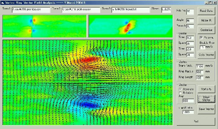
We are presently carrying out the first measurements with an Ultrasonic Velocity Profiler (UVP). These first experiments are for rings in the non-rotating system. Colleagues from Hokkaido University with whom we collaborate are currently visiting us and have brought the UVP system with them. As soon as they are gone we will try to get some dye-visualization experiments done in the large facility. In the meantime here is a plot showing you a velocity-vector field as measured with the UVP system. On the plot the ring propagates from left to right; corresponding to top to bottom in the water tank.
[The results of the measurements from March have now been summrised see: Murai, Y., Kitaura, H., Xiao, Z., Thomas, P.J., Takeda, Y. (2004) Study of Vortex-Ring Dynamics Using UVP In: Proceedings of the Fourth International Symposium on Ultrasonic Doppler Method for Fluid Mechanics and Fluid Engineering , Hokkaido University, Sapporo, 6-8 September, pp. 3-8, PDF file of paper .]
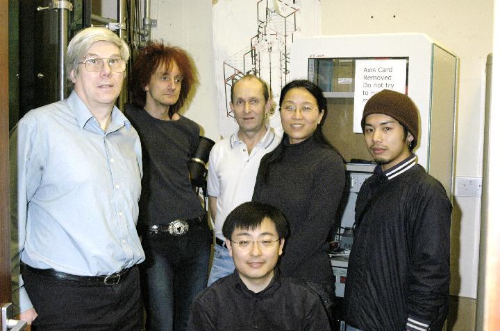
Below is a photo showing our team. From left to right in back row are: John Roe (designed the facility), Peter J. Thomas, Paul Hackett (built many parts for the facility and assembled it), Zhiying Xiao Ellis, Hidekazu Kitaura (Hokkaido University), sitting in the front is Yuichi Murai (Hokkaido University)
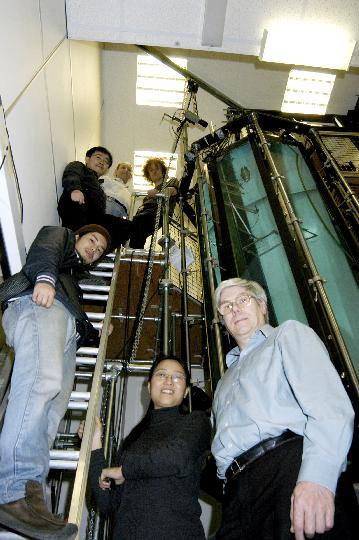
Below another photo showing the team on the ladder leading up to the top of the facility. The photo helps illustrating the scale of the experimental set-up. From top (left) to bottom are: Peter J. Thomas, Paul Hackett, Yuichi Murai, Hidekazu Kitaura, Zhiying Xiao Ellis, John Roe.
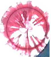
18-19 March 2004: We played around some more and improved/extended the filming capabilities a bit. Here is a video showing a front view (7 MBytes) similar to the one in our first test video above. We are cheating a bit though. In order to improve the visibility of the ring in front of the nozzle we built a little flap which we insert between the ring and the nozzle to cover it after the vortex has propagated about 10 cm away from the nozzle. This will of course influence the ring motion but these first videos here are only for illustration. One can, however, see the typical wavy instabilities developing on the initially circular vortex core.
Next are a few videos showing vortex rings from the side:
- Side View 1 (5 MBytes),
- Side View 2 (2.5 MBytes),
- Side View 3 - Zoomed In (2.5 MBytes),
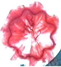
- Side View 4 - Recorded with two cameras. The video shows wavy instability from side. One can clearly see that the waves protrude out of the plane of symmetry of the vortex ring (3.2 MBytes).
After our colleagues from Japan had left we planned to do first experiments in the rotating facility. However, we encountered various technical 'problems' and nearly experienced a major desaster. All problems have now (23 August 2004) been sorted out and we have started first experiments on vortex rings in the rotating facility. Here are some videos showing the facility during first rotating experiments:
We also have photographs and videos showing vortex rings in rotating systems. Some of these will appear here after they have been published in the literature etc. Most of these videos and photographs of rings in rotating systems show flow features that have possibly never been recorded by a human beeing previously. Hence, we do not want these videos and photographs to be out in the public domain yet.
Our colleagues from Japan will be back at the end of September to carry out UVP measurements on the rotating facility. More soon...
The Japanese colleagues were back in September as planned. We are currently analysing the data from the first rotating experiments and we are preparing a manuscript summarizing the results from the experiments in March 2004.
A lot of things have happened! Mark Brend, who does his PhD research on vortex rings, has installed a PIV system on the turntable. He also developed numerous other things that make life easier. For instance, Mark automated the whole process of shooting vortex rings. For his research he has to average data of 100s of rings. He automated the experiments and the data collection. He now only needs to press a button and then go home and the experiments run while he is away. Here are two videos of the facility in its present state. The second video is the more dramatic one showing the laser of the PIV system flashing away while a ring is moving downwards in the rotating tank and two moving PIV cameras track the ring motion downwards... Turn your sound on, Mark is commenting on what is seen and happening in the videos...
(All photographs by Graham Canham, Photographic Unit, School of Engineering, University of Warwick. Videos filmed by Mark Brend, Graham Canham, Peter J. Thomas videos edited by Graham Canham)
Return to Index
