
IV
IV measurements are a process to determine devices characteristics and performance. Depending on the device in hands we will attain different information.
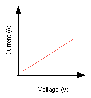
lets consider a ohmic device, that is, is obeys Ohm law, then as the equation shows we would obtain a linear relation between voltage and current, as showed:
The resistance we measure has a contribution from the sample, the wires and the contacts:
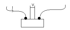
In order to minimise the contact and wires resistances the measurements are usually done with four probes;
We are initially considering diodes. Below is sketch an IV curve. from observing the curve we can determine if we have a good quality device, since the bigger is, better will the device perform. The threshold voltage is taken from the extrapolation to V=0 of the IV curve in forward bias.
Another parameter that is possible to take is the Schoottky barrier height. A sketch of the band structure can be seen below:
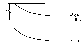
In order to get the barrier height (φB) we need to consider the thermionic current voltage relationship:
where Is is the saturation current and
from this last equation we get
with being the area of the diode and A*=120(m*/m). If we plot a semilog curve of Isvs. V and extrapolate the curve to V=0 we will get φB for zero bias.
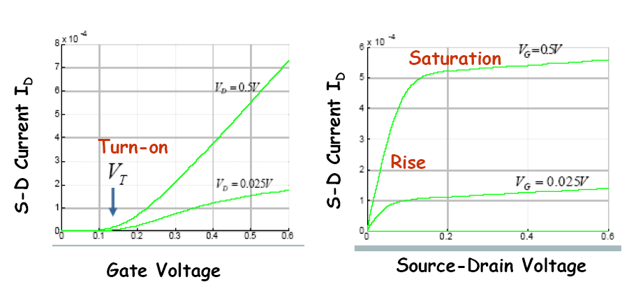
Lets consider now a MOSFET. Below is a sketch of one:
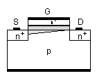
where S is the source, D the drain and G the gate. One measure we can make is to measure the current at the drain and the source while we apply a constant voltage in the gate and a variable voltage along the drain and the source. What we will obtain is:
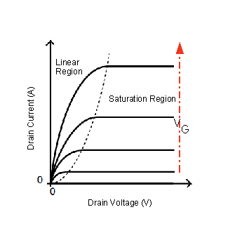
In this figure we can see two different regions: the linear region and the saturation region. In the linear region the conduction channel acts like a resistor. if we continue to increase the voltage the channel potential will reduce the current, translating in the lost of linearity, if we continue to increase the voltage we will get to a point where the inversion charge reaches zero and we no longer see a change in the current, we reach the saturation regime.
The threshold voltage is the gate bias at which the devices turn on. And, it can be determine from the transfer characteristic, for that we need to measure the drain current while we change the gate voltage and extrapolate the curve to V=0. If we then plot the same curve in a semi log scale we will get the subthreshold swing.
There are many parameters could be extracted from IV measurement such as thershold voltage ,subthershold slope and resistance which will discuss in next section.
Reference
1. D. K. Schroder, Semiconductor material and device characterization (3rd Ed.) John Wiley & Sons.