
High Frequency Flexural Ultrasonic Transducers
This research project began as an Advanced Fellowship funded from 2016 to 2021 by the Engineering and Physical Sciences Research Council (EPSRC), grant number EP/N025393/1. It is now a multi-institution collaboration between the Universities of Warwick, through Principal Investigator and CIU Director Prof Steve Dixon, PhD candidate Will Somerset, and Technician Jonathan Harrington, Portsmouth via Senior Lecturer Dr Lei Kang, and Glasgow, through Lecturer in Ultrasonics Dr Andrew Feeney.
-
Project Goals and Overview
-
The Flexural Ultrasonic Transducer
-
Characterisation of Transducer Performance
-
The Wideband Electromagnetic Dynamic Acoustic Transducer: WEMDAT
- Flexural Ultrasonic Transducers at Elevated Pressure Levels
-
HiFFUT Design Tool
-
Acoustic Levitation
- Industrial Collaboration
-
Documents and Downloads
-
Key Publications
-
Professional Engagement and Outreach Activities
-
Funding Information and Contact Details
1. Project Goals and Overview
Flexural ultrasonic transducers are designed and operated exclusively in ambient atmospheric conditions. They are used up to around 50 kHz, where the wavelengths in fluids are relatively long, thus reducing measurement resolution. Flexural ultrasonic transducers which can operate effectively at higher frequencies are therefore desirable, but also to withstand higher pressure and temperature levels associated with more hostile environments encountered in many industrial and aerospace applications. The major objective of this research is the development of high frequency flexural ultrasonic transducers (HiFFUTs) for operation with high efficiency in both liquid and gas environments. Target operating conditions with respect to pressure are outlined in Table 1, and relating to temperature in Table 2.
| Example Application | Target Pressure Tolerance (bar) |
| Domestic Water Metering | 20 |
| Industrial Gas Metering | 300 |
| Industrial Flow Metering | ≥ 300 |
| Example Environment | Target Temperature Tolerance (°C) |
| Oil Production | 120 |
| District Heating | 250 |
| Petrochemical | 350-450 |
| Power Plants | 560 |
We analyse both commercial and custom-made transducers, and we fabricate our own devices within our group, to meet the requirements of the project. We use the latest vibration characterisation techniques such as sensor systems in transmit-receive mode, acoustic microphones, and laser Doppler vibrometry, to assess the performance of all of our devices, and are working with industry partners, detailed below, for qualification in practical application.
2. The Flexural Ultrasonic Transducer
The flexural ultrasonic transducer is a unimorph device which typically consists of a piezoelectric ceramic disc bonded to a metal cap. The cap can be considered as an edge-clamped plate. The piezoelectric ceramic is coupled to the metal cap through a bonding agent, and the vibration of the ceramic thereby induces bending modes of the cap. One significant advantage of the flexural ultrasonic transducer over alternative ultrasonic transducers such as the pMUT or cMUT is that the flexural ultrasonic transducer is not subject to impedance mismatch since it generates ultrasound through a flexing membrane. This enables the transducer to couple effectively to low impedance media, and to operate efficiently with low input voltage. Flexural ultrasonic transducers have been utilised for a variety of applications, including in proximity sensing environments such as car-parking systems, and for non-destructive evaluation. The classical assembly of a flexural ultrasonic transducer is shown in Figure 1.
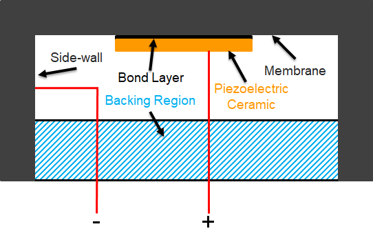
Figure 1: Cutaway assembly schematic for a typical flexural ultrasonic transducer.
The mode shapes shown in this research conform to (m,n), where m designates the number of nodal radii and n indicates the number of nodal diameters. The fundamental modes of vibration of a flexural ultrasonic transducer are shown in Figure 2, depicting two axisymmetric modes, termed (0,0) and (1,0), and two asymmetric modes, designated as (0,1) and (1,1). Higher order modes can also be exploited, such as the (2,0) axisymmetric mode, but this can involve reduced efficiency unless the transducer is specifically designed to operate at that mode.
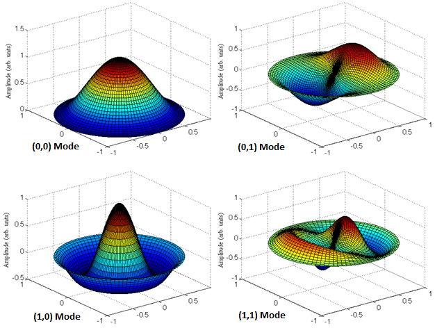
Figure 2: Simulated edge-clamped plate modes representing the vibration of a flexural ultrasonic transducer.
The vibration characteristics of the flexural ultrasonic transducer are significantly dependent on the geometrical and material properties of the cap. The transverse displacement w of the cap membrane can be determined through the following differential equation, in terms of rigidity D, radius x, membrane thickness h, and cap with material density ρ:
The rigidity of the cap membrane can be calculated using the following relationship, where E is the Young's modulus and υ is the Poisson's ratio:
The resonance frequency f can hence be determined using the following equation, where λ is a Bessel function constant relating to the mode shape, a is the cap membrane radius for the boundary condition x=a:
3. Characterisation of Transducer Performance
The dynamic characterisation of flexural ultrasonic transducers has been extensively studied during the course of this project so far, and progress in HiFFUT development has already been made, including for high temperature environments towards 200°C. Downloads and publications are available at the bottom of this web-page, but some key outcomes are depicted in the following figures.
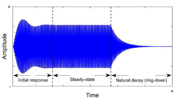
Figure 3: Discretised vibration response of a flexural ultrasonic transducer from a burst sine excitation.
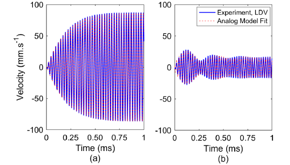
Figure 4: The vibration response of a flexural ultrasonic transducer in the initial response zone (see Figure 3), compared with the analog model fit computed from the derived equation shown below. This is real laser Doppler vibrometry (LDV) data compared with the response computed using the characteristic equation, for (a) a resonance 40 kHz drive frequency, and (b) an off-resonance 44 kHz drive frequency.
In this equation, the F magnitudes relate to the resonant amplitude of the transducer, E is the forced vibration amplitude, and α is related to the system damping.
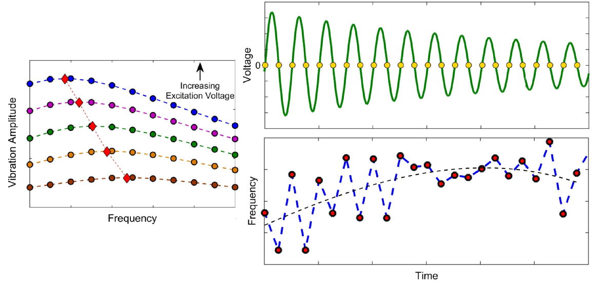
Figure 5: Nonlinearity in the dynamic response of a flexural ultrasonic transducer operating at steady-state (left) and natural decay (right), showing resonance frequency drift with increasing excitation voltage.
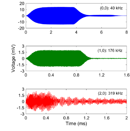
Figure 6: Measurement of high frequency and higher order vibration modes of an aluminium flexural ultrasonic transducer in air, at a distance of 0.5 metres with a burst-sine input of 10 VP-P and 150 cycles. This data was published in IEEE Sensors Journal in 2018. Note the difference in time scales for clarity.
4. The Wideband Electromagnetic Dynamic Acoustic Transducer: WEMDAT
We have developed a new type of ultrasound transducer, called the wideband electromagnetic dynamic acoustic transducer, or WEMDAT. Achieving a high level of energy transmission over a wide frequency range is a challenge which has restricted the application of many types of air-coupled ultrasonic transducers. Conventional transducer configurations such as the pMUT or classical design of flexural ultrasonic transducer can be considered as narrowband. The WEMDAT operates through a combination of electromagnetic induction and Lorentz force with dynamic behaviour of a micro-scale-thick conductive film. The WEMDAT is compatible with both low and high power inputs and operates efficiently as a wideband transmitter from 46.4 kHz to 144.6 kHz with a good level of directivity. The WEMDAT can also operate effectively as a wideband ultrasonic receiver through the measurement in a pitch-catch configuration. The WEMDAT prototypes possess an adjustable drive coil lift-off distance from the active membrane, providing flexibility for optimizing the sensitivity of the transducers for different input levels. The performance of the WEMDATs can be optimized, showing significant potential for air-coupled ultrasonic applications. The WEMDAT also represents a realistic alternative to conventional microphone systems. The images included in this section have been taken from our research published in Applied Physics Letters in 2019, and a patent has been filed for this invention. The link to the research paper can be found at the bottom of this web-page.
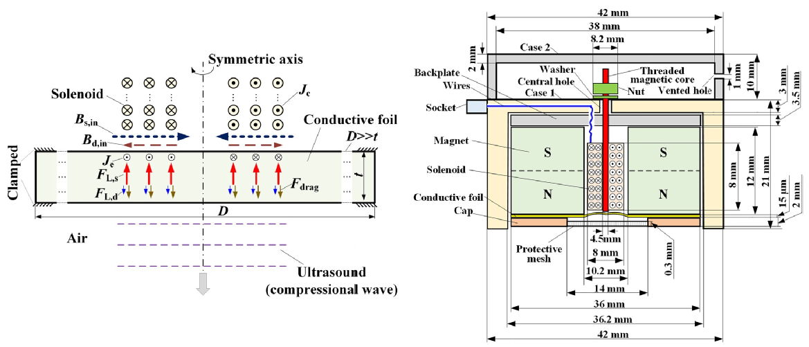
Figure 7: Operating principle (left) and general assembly schematic (right) for the WEMDAT.
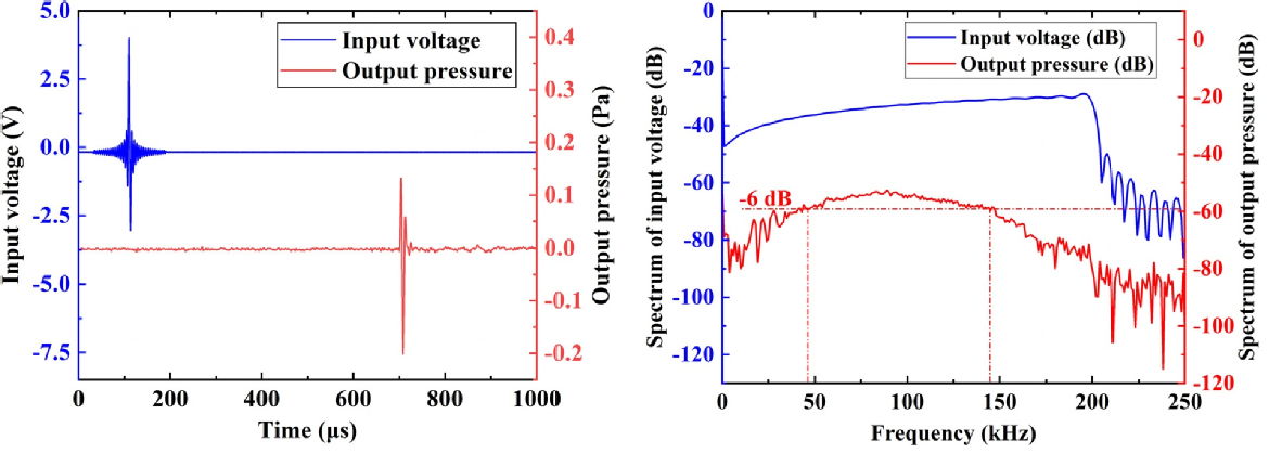
Figure 8: The WEMDAT as an ultrasound generator (left) and its frequency response (right).
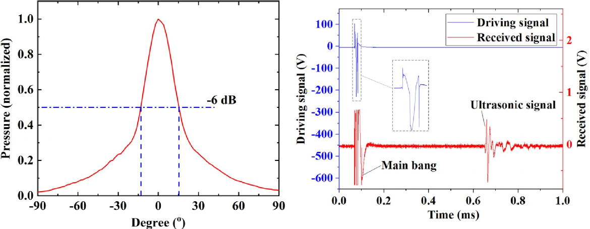
Figure 9: The radiation pattern (left) and dual-device pitch-catch response (right) for the WEMDAT.
5. Flexural Ultrasonic Transducers at Elevated Pressure Levels
Flexural ultrasonic transducers have been tested in air environments at elevated pressure levels using a custom pressure chamber. The commercial type Multicomp 40 kHz transducer has been the subject of the fundamental studies. The principal limitation of commercially available flexural ultrasonic transducers is that they comprise a silicone-type seal which reduces their suitability for operation at elevated levels of environmental pressure. As external pressure is raised, an associated pressure imbalance develops with the internal cavity of the transducer until a leak occurs. A modified form of this transducer which is vented has also been investigated as one solution to this limitation. The purpose of venting is to enable the balancing of pressure on either side of the transducer membrane. A selection of results are shown in Figures 10 and 11 below which show the dynamic performance of different flexural ultrasonic transducers at elevated pressure levels. The vented flexural ultrasonic transducers exhibit stable dynamic properties.
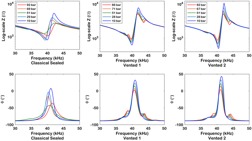
Figure 10: Electrical impedance spectra of different flexural ultrasonic transducers at elevated air pressures.
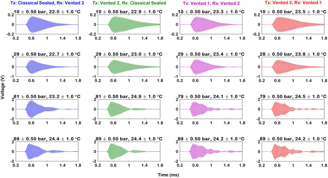
Figure 11: A-scans from different flexural ultrasonic transducers in pitch-catch at elevated air pressures.
6. HiFFUT Design Tool
This section provides an expedient and rapid estimator for basic HiFFUT design and operating parameters, for the fundamental axisymmetric and asymmetric modes of vibration, and for a selection of standard cap materials. This estimator tool is constructed from the underlying mathematics of the vibration modes for an edge-clamped plate, which are summarised above, to generate the operating frequency for a designated mode of vibration, accounting for membrane rigidity in each case. The higher the rigidity, the less compliant the membrane, and therefore less efficient for propagating ultrasound energy. This is important to consider in the design of HiFFUTs. This tool is strictly an estimator and therefore should be used as a guideline only. This is because the vibration characteristics and dynamic performance of a HiFFUT will not precisely match that of an edge-clamped plate. For example, this estimator does not account for the properties of the piezoelectric ceramic. Finite element methods are strongly recommended for comprehensive HiFFUT design.
To use this tool, a minimum of three membrane parameters are required, comprising the diameter, thickness, and material type. A selection of standard HiFFUT cap materials has been built into the tool for convenience. A key feature of this tool is its ability to generate modal frequencies based on custom material properties. To enter a custom material, simply enter its material properties in the empty fields, and select "Custom", which is located under the HiFFUT Membrane Material drop-down menu. Note that when specifying the membrane diameter, this does not include the side-wall geometry. Once the relevant tool fields are populated, the resonance frequency of a specific mode can be determined by selecting from the "Mode of Vibration" drop-down menu, before selecting "Calculate".
The estimator is provided below, followed by the supplementary information important for the practical design and fabrication of HiFFUTs. Properties for selected cap membrane materials are shown in Table 3 for reference.
Estimator of HiFFUT Operating Frequency
| HiFFUT Membrane Diameter (mm): | |
| HiFFUT Membrane Thickness (mm): | |
| Density (kg/m3): | |
| Young's Modulus (GPa): | |
| Poisson's Ratio: | |
| HiFFUT Membrane Material: | |
| Mode of Vibration: | |
| Modal Frequency (kHz): |
| Material | Young's Modulus (GPa) | Density (kg/m3) | Poisson's Ratio |
| Acrylonitrile Butadiene Styrene (ABS) | 2.62 | 1050 | 0.35 |
| Aluminium | 69 | 2700 | 0.33 |
| Duraluminium | 73 | 2800 | 0.34 |
| 30% Carbon Fibre Polyetheretherketone (PEEK) | 24 | 1400 | 0.40 |
| Polycarbonate | 21.4 | 1200 | 0.35 |
| Stainless Steel | 190 | 7960 | 0.305 |
| Titanium | 116 | 4510 | 0.32 |
The key design considerations for HiFFUTs are:
- Amplitude of Ultrasound. The achievable vibration amplitude of the HiFFUT depends on the cap material and physical dimensions of the HiFFUT and its components. A sufficiently robust transducer design will be required, to ensure the ability to operate the transducer at high amplitudes.
- Backing Material. The choice of backing material, and backing layer thickness, both depend on the dimensions of the cap material and HiFFUT dimensions.
- Boundary Condition. This is an essential consideration. Even minor differences in how a HiFFUT is supported can significantly affect its vibration characteristics. Careful control of the boundary conditions must be ensured for repeatable measurement.
- Cap Specification. The elastic properties of the cap material affect the vibration response of the HiFFUT, where the Young's modulus, Poissons ratio, and density of the material are most significant. There is flexibility in the choice of cap material, the most popular being stainless steel, aluminium and titanium, as provided in the design tool. The material and the cap dimensions will affect the vibration behaviour of the HiFFUT, but the vibration motion predominantly relies on how the membrane layer is defined, where the side-wall of the cap provides far less influence. Higher pressure environments may necessitate thicker membranes, depending on the design, but the cost of this is reduced compliance, and hence a lower efficiency. As the cap membrane diameter is increased, the magnitudes of the modal frequencies generally reduce. A compromise between cap membrane diameter and resonance frequency is hence required. A larger cap diameter enables a higher amplitude of vibration to be achieved for a specific excitation signal, but for a lower resonance frequency. However, a cap membrane diameter which is too small will make transducer fabrication difficult, for example with respect to soldering electrode connections.
- Driving Mechanism. High pressure and temperature levels restrict the types of active driver which can be efficiently used in HiFFUTs. Strategies for shielding piezoelectric ceramics should be considered, or the use of alternative forms of active driver materials.
- Efficiency. The thickness of the HiFFUT cap and the diameter of the radiating membrane both affect the resonance frequency. The mechanisms by which these parameters affect resonance frequency have been reported, but less is known regarding how they affect transducer efficiency.
- Environmental Conditions. This should be determined prior to any design process, for example with respect to pressure or temperature. The type of fluid will also be important to define, for example air, oil, or gas.
- Frequency and Mode of Operation. The operating frequency can be estimated prior to HiFFUT design using the tool above, by manipulating the cap membrane material and dimensions. One solution may be to exploit higher order vibration modes, such as the (1,0) or (2,0) modes rather than the (0,0) mode, in the generation of high frequencies.
- Geometrical Dependencies. the thickness of the driver element, such as the piezoelectric ceramic, should be lower than that of the cap, to ensure sufficient flexure in operation in the generation of the axisymmetric modes of vibration. However, the cap cannot be of a thickness which restricts the bending motion to generate the mode shapes.
- Loss. The design and simulation of transducer performance should consider ceramic dielectric loss, in addition to internal mechanical loss. The electromechanical coupling coefficient is a useful property for assessing HiFFUT performance.
- Mechanical Coupling. The problems surrounding the bonding of flextensional and cymbal type transducers has been extensively reported. Transducers can be very sensitive to bond layer inhomogeneities, differences in deposited thickness, and the type of bonding agent used. The method of bond layer deposition, and any pre-treatment such as degassing and surface preparation, should be considered. Alternatively, an entirely different coupling mechanism may be an appropriate solution.
7. Acoustic Levitation
Acoustic levitation has been achieved using flexural ultrasonic transducers operating at 40 kHz, with a custom portable, hand-held system design as shown below. Our levitation system can be oriented in different ways, from vertical through to horizontal, maintaining the levitation of the particles, and the height between the top and lowermost supports can be adjusted. The acoustic levitation system is shown in Figure 12, and a video of our system in action can be found by clicking here.
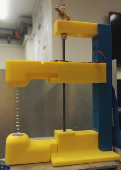
Figure 12: The acoustic levitation system based on flexural ultrasonic transducers.
8. Industrial Collaboration
This research is being conducted with direct interaction with key industry organisations.

Dynoptic Systems Ltd: www.dynoptic.com
EES Research Ltd: www.eesresearch.com
EES Research Ltd is a UK owned Research & Development company with over 25 years experience developing process measurement and control instrumentation for a diverse range of industries. Their expertise includes ultrasonic, capacitance and radar techniques for level and flow measurement. EES Research has experience in many areas including water, mining, petrochemical, transport, information systems, and communications systems. Contact: Dr Noel Kerr, Managing Director, Email: noel at eesresearch dot com, Telephone: +44(0)7971 273000, Headquarters: EES Research Ltd, Lochiel, Llaneilian Rd, Amlwch Port, Anglesey, LL68 9HU, United Kingdom
FLEXIM Instruments Ltd: www.flexim.com
Katronic Technologies Ltd: www.katronic.com
Katronic develop and manufacture portable and fixed installation ultrasonic flowmeters with the intention that the measurement of flow should be quick, easy and straightforward. Katronic ultrasonic flowmeters can measure on pipes of all standard acoustically conductive materials over a large diameter range and are suitable for process liquids from pure water to chemicals and effluents. Contact: Rob Turner, Engineering Manager
National Nuclear Laboratory: www.nnl.co.uk
9. Documents and Downloads
Key documents, publications and resources are provided in this section for download. In addition, documents relating to the regular project meetings with the industrial partners have been made available. Raw data sets associated with each journal publication are made available through a link provided in each article.
- IEEE IUS Publication - 2021 Link to Website
- Journal of Physics (D) Publication - 2022 Link to Website
- UIA Poster Presentation - 2021
- Journal of Physics (D) Publication - 2021 Link to Website
- IEEE Sensors Journal Publication 2 - 2020 Link to Website
- IEEE Sensors Journal Publication 1 - 2020 Link to Website
- POMA Publication 2 - 2020 Link to Website
- POMA Publication 1 - 2020 Link to Website
- IEEE IUS Publication 2 - 2019 Link to Website
- IEEE IUS Publication 1 - 2019 Link to Website
- ICU 2019 Bruges Presentation 2 - Dr Andrew Feeney Link to Website
- ICU 2019 Bruges Presentation 1 - Dr Andrew Feeney Link to Website
- Sensors Publication 2 - 2019 Link to Website
- Sensors Publication 1 - 2019 Link to Website
- IEEE Sensors Journal Publication - 2019 Link to Website
- Applied Physics Letters Publication - 2019 Link to Website
- March 2019 CIU Meeting Presentation - Dr Andrew Feeney
- IEEE IUS Publication - 2018 Link to Website
- Update Report - October 2018
- Minutes from September 2018 Meeting
- September 2018 Meeting Presentation - Dr Andrew Feeney
- IEEE Sensors Journal Publication - 2018 Link to Website
- UIA 47 Atlanta Presentation - Dr Andrew Feeney
- April 2018 CIU Meeting Presentation - Dr Lei Kang
- April 2018 CIU Meeting Presentation - Dr Andrew Feeney
- Update Report - March 2018
- Minutes from March 2018 Meeting
- March 2018 Meeting Presentation - Dr Lei Kang
- March 2018 Meeting Presentation - Dr Andrew Feeney
- Sensors Publication - 2018 Link to Website
- IEEE Sensors Letters Publication - 2018 Link to Website
- POMA Publication 3 - 2017 Link to Website
- POMA Publication 2 - 2017 Link to Website
- POMA Publication 1 - 2017 Link to Website
- ICU 2017 Poster - December 2017
- ICU 2017 Hawaii Presentation 2 - Dr Andrew Feeney Link to Website
- ICU 2017 Hawaii Presentation 1 - Dr Andrew Feeney Link to Website
- IEEE IUS Publication - 2017 Link to Website
- Update Report - September 2017
- Minutes from September 2017 Meeting
- September 2017 Meeting Presentation - Dr Andrew Feeney
- Minutes from April 2017 Meeting
- Update Report - March 2017
- Applied Physics Letters Publication - 2017 Link to Website
- April 2017 Meeting Presentation - Dr Andrew Feeney
- 3rd Flow Measurement Institute Conference Poster - Coventry University - July 2017
- Minutes from December 2016 Kick-Off Meeting
- December 2016 Kick-Off Meeting Presentation - Dr Andrew Feeney
10. Key Publications
- W.E. Somerset, A. Feeney, L. Kang, Z. Li, and S. Dixon, "Oil filled flexural ultrasonic transducers for resilience in environments of elevated pressure", Proceedings of the 2021 IEEE International Ultrasonics Symposium, Xi'an, China, September 2021.
- A. Feeney, L. Kang, and S. Dixon, "Higher order modal dynamics of the flexural ultrasonic transducer", Journal of Physics D: Applied Physics, vol. 55, p. 07LT01, 2022.
- S. Dixon, L. Kang, A. Feeney, and W.E. Somerset, "Active damping of ultrasonic receiving sensors through engineered pressure waves", Journal of Physics D: Applied Physics, vol. 54, no. 13, p. 13LT01, 2021.
- L. Kang, A. Feeney, and S. Dixon, "The high frequency flexural ultrasonic transducer for transmitting and receiving ultrasound in air", IEEE Sensors Journal, vol. 20, no. 14, pp. 7653-7660, 2020.
- A. Feeney, L. Kang, G. Rowlands, and S. Dixon, "The nonlinear dynamics of flexural ultrasonic transducers", Proceedings of Meetings on Acoustics, vol. 38, no. 1, 045015, 2020.
- A. Feeney, L. Kang, W.E. Somerset, and S. Dixon, "Venting in the comparative study of flexural ultrasonic transducers to improve resilience at elevated environmental pressure levels", IEEE Sensors Journal, vol. 20, no. 11, pp. 5776-5784, 2020.
- A. Feeney, L. Kang, W.E. Somerset, and S. Dixon, "Measurement using flexural ultrasonic transducers in high pressure environments", Proceedings of Meetings on Acoustics, vol. 38, no. 1, 045014, 2020.
- L. Kang, A. Feeney, W. Somerset, and S. Dixon, "Wideband electromagnetic dynamic acoustic transducer as a standard acoustic source for air-coupled ultrasonic sensors", Proceedings of the 2019 IEEE International Ultrasonics Symposium, Glasgow, UK, October 2019.
- L. Kang, A. Feeney, W. Somerset, R. Su, D. Lines, S.N. Ramadas, and S. Dixon, "A novel mathematical model for transit-time ultrasonic flow measurement", Proceedings of the 2019 IEEE International Ultrasonics Symposium, Glasgow, UK, October 2019.
- L. Kang, A. Feeney, R. Su, D. Lines, S.N. Ramadas, G. Rowlands, and S. Dixon, "Flow velocity measurement using a spatial averaging method with two-dimensional flexural ultrasonic array technology", Sensors, vol. 19, no. 21, 4786, pp. 1-13, 2019.
- A. Feeney, L. Kang, W.E. Somerset, and S. Dixon, "The influence of air pressure on the dynamics of flexural ultrasonic transducers", Sensors, vol. 19, no. 21, 4710, pp. 1-16, 2019.
- A. Feeney, L. Kang, G. Rowlands, L. Zhou, and S. Dixon, "Dynamic nonlinearity in piezoelectric flexural ultrasonic transducers", IEEE Sensors Journal, vol. 19, no. 15, pp. 6056 - 6066, 2019.
- L. Kang, A. Feeney, and S. Dixon, "Wideband electromagnetic dynamic acoustic transducers (WEMDATs) for air-coupled ultrasonic applications", Applied Physics Letters, vol. 114, no. 5, p. 053505, 2019.
- L. Kang, A. Feeney, and S. Dixon, "Analysis of influence of inconsistent performances of array elements on flexural ultrasonic phased array for measurement of ultrasound in fluids", Proceedings of the 2018 IEEE International Ultrasonics Symposium, Kobe, Japan, October 2018.
- A. Feeney, L. Kang, and S. Dixon, "High frequency measurement of ultrasound using flexural ultrasonic transducers", IEEE Sensors Journal, vol. 18, no. 13, pp. 5238 - 5244, 2018.
- A. Feeney, L. Kang, and S. Dixon, "Nonlinearity in the dynamic response of flexural ultrasonic transducers", IEEE Sensors Letters, vol. 2, no. 1, pp. 1-4, 2018.
- A. Feeney, L. Kang, G. Rowlands, and S. Dixon, "The dynamic performance of flexural ultrasonic transducers", Sensors, vol. 18, no. 1, 270, pp. 1-14, 2018.
- A. Feeney, L. Kang, G. Rowlands, and S. Dixon, "HiFFUTs for high temperature ultrasound", Proceedings of Meetings on Acoustics, vol. 32, no. 1, 045003, 2017.
- A. Feeney, L. Kang, G. Rowlands, and S. Dixon, "Dynamic characteristics of flexural ultrasonic transducers", Proceedings of Meetings on Acoustics, vol. 32, no. 1, 045002, 2017.
- L. Kang, A. Feeney, R. Su, D. Lines, A. Jäger, H. Wang, Y. Arnaudov, S.N. Ramadas, M. Kupnik, and S. Dixon, "Two-dimensional flexural ultrasonic phased array for flow measurement", Proceedings of the 2017 IEEE International Ultrasonics Symposium, Washington D.C., USA, September 2017.
- S. Dixon, L. Kang, M. Ginestier, C. Wells, G. Rowlands, and A. Feeney, "The electro-mechanical behaviour of flexural ultrasonic transducers", Applied Physics Letters, vol. 110, no. 22, p.223502, 2017.
- T.J.R. Eriksson, S.N. Ramadas, and S.M. Dixon, "Experimental and simulation characterisation of flexural vibration modes in unimorph ultrasound transducers", Ultrasonics, vol. 65, pp. 242-248, 2016.
- T.J.R. Eriksson, S.M. Dixon, and S.N. Ramadas, "Metal cap flexural transducers for air-coupled ultrasonics", In 41st Annual Review of Progress in Quantitative Nondestructive Evaluation: Volume 34, AIP Publishing, vol. 1650, no. 1, pp. 1287-1291, 2015.
- T.J.R. Eriksson, S.M. Dixon, and S.N. Ramadas, "Flexural mode metal cap transducer design for specific frequency air coupled ultrasound generation", In 2013 IEEE International Ultrasonics Symposium (IUS), pp. 1602-1605, 2013.
11. Professional Engagement and Outreach Activities
We demonstrate our research, and other ultrasound-related science, to both our peers and the general public on a regular basis. A selection of these activities are shown below.
Engagement with Industry:
--------------------------------------------------------------------------------------------------------------
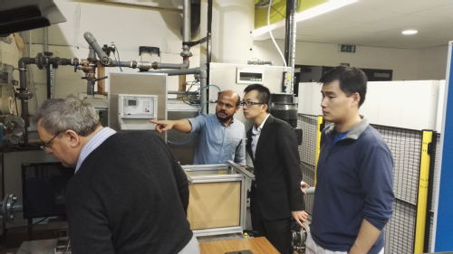
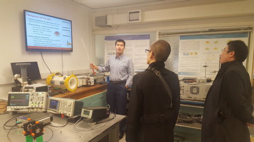
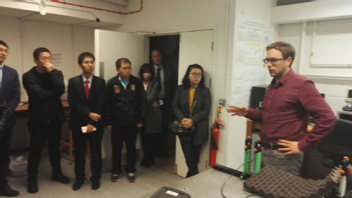
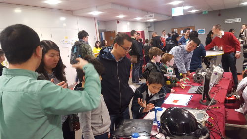
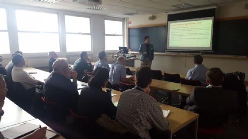
Demonstration to delegates from China's Harbin Institute of Technology in November 2017:
--------------------------------------------------------------------------------------------------------------
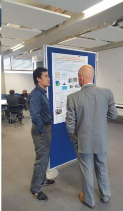
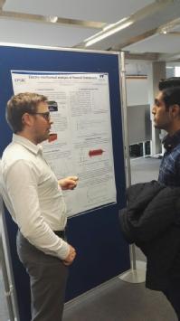
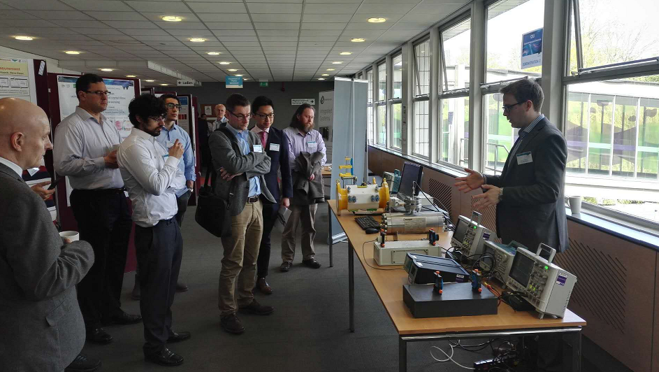
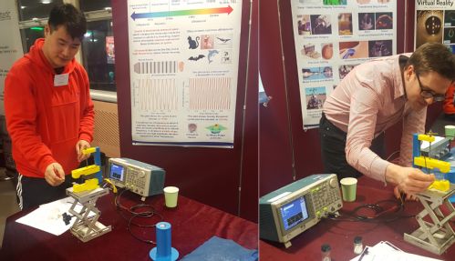
Demonstration of Research at the 3rd Flow Measurement Institute Conference in July 2017:
--------------------------------------------------------------------------------------------------------------
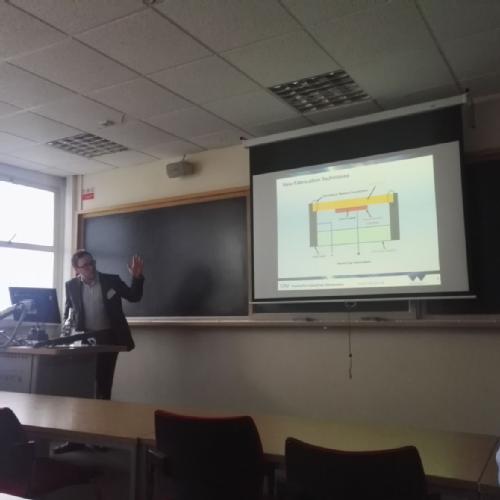
Presentation at the RCNDE Early Career Researcher Symposium in June 2017:
--------------------------------------------------------------------------------------------------------------
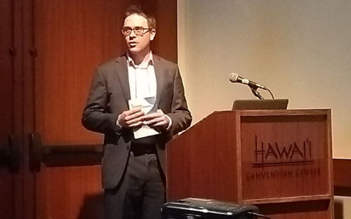
Presentation of flexural ultrasonic transducer dynamics research to the International Congress on Ultrasonics in Hawaii, in December 2017:
--------------------------------------------------------------------------------------------------------------
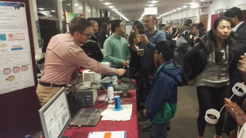
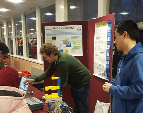
STEM outreach at the XMaS Science Gala in January 2018:
--------------------------------------------------------------------------------------------------------------
CIU Open Day Meeting in April 2018:
--------------------------------------------------------------------------------------------------------------
STEM outreach at the XMaS Science Gala in January 2019:
--------------------------------------------------------------------------------------------------------------
CIU Open Day Meeting in March 2019:
--------------------------------------------------------------------------------------------------------------
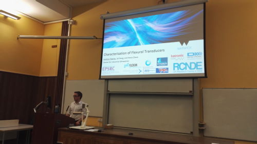
Presentation of how flexural ultrasonic transducers can be designed for elevated pressure environments to the International Congress on Ultrasonics in Bruges, in September 2019:
--------------------------------------------------------------------------------------------------------------
STEM outreach at the XMaS Science Gala in February 2020:
12. Funding Information and Contact Details
EPSRC Grants on the Web information: https://gow.epsrc.ukri.org/NGBOViewGrant.aspx?GrantRef=EP/N025393/1
The information on this web-page is managed and regularly updated by the research team.
- Email: s dot m dot dixon at warwick dot ac dot uk.
- Contact Number: +44(0)24 765 73877
- Web-page: https://warwick.ac.uk/fac/sci/physics/staff/academic/dixon_s/